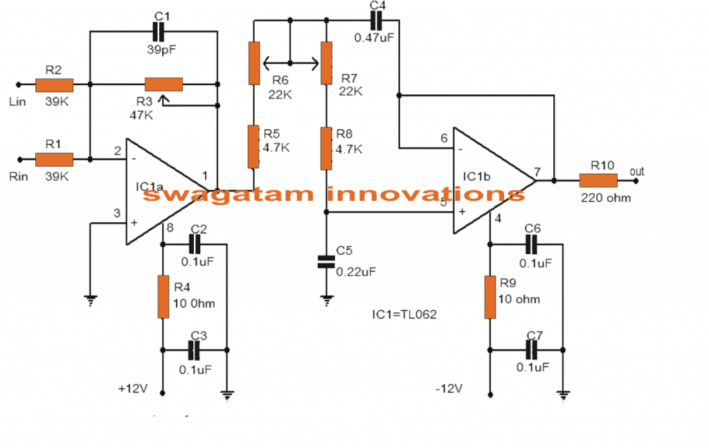
Band Reject Filter Circuit

Band reject filter circuit
A Band Stop Filter, also sometimes called a notch or band reject filter allows a specific range of frequencies to not pass to the output, while allowing lower and higher frequencies to pass with little attenuation.
How do you reject a band filter?
To create band-pass and band-reject filters, you need two cutoff frequencies, a lower limit fL and a higher limit fH. The combined filters inherit the transition bandwidth (or roll-off), which might be different at each end, from the low-pass and high-pass filters that were used to build it.
What is band-pass and band reject filter?
A band-pass filter, in contrast, passes frequencies that fall only within a relatively narrow range, and a band-reject filter (also called a band-stop or notch filter) passes all frequencies except those that fall within a relatively narrow range.
What is band-pass filter circuit?
A bandpass filter is an electronic device or circuit that allows signals between two specific frequencies to pass, but that discriminates against signals at other frequencies.
Where are band reject filters used?
Band Reject Filter Applications
- The filter is used mainly in public address systems and speaker systems for ensuring good quality audio.
- The devices are a crucial part of telephone technology, as they are used as line noise reducers in case of signal transmission.
Why is band-pass filter used?
Band-pass filter functions are used where it is desired to transmit signals in a certain band of frequencies and block signals of lower and higher frequencies. This is what is done in “tuning” a desired frequency, such as a radio or television signal.
What are the ideal characteristics of band rejection filter?
An ideal band rejection filter rejects completely all the signals of frequencies within a frequency band (ω2−ω1) radians per second and transmits all the signals of frequencies outside the frequency band without any distortion. In this case, the frequency band (ω2−ω1) is called the rejection band.
How many band reject filters are present?
Explanation: Band-reject filters are also called as band elimination filters. They are classified into two types. ii) Narrow band-reject filter.
What is the difference between a low-pass filter and a band-pass filter?
A bandpass filter allows signals between two specific frequencies to pass, but that discriminates against signals at certain frequencies. A lopass filter is a filter that passes signals with a frequency lower than a certain cutoff frequency and minimizes signals with frequencies higher than the cutoff.
Is band stop and band reject filter same?
The band stop filter, also known as a band reject filter, passes all frequencies with the exception of those within a specified stop band which are greatly attenuated.
What are the advantages and disadvantages of band-pass filter?
Band Pass Filter is a filter used in signal processing to allow wanted frequency components and to remove the unwanted components from the signals. ... Disadvantages
- Active Filters requires power supply.
- Highly sensitive to variations in circuit components.
- They have inherent insertion loss.
Why is it called a band block filter?
The name itself indicates that it will stop a particular band of frequencies. Since it eliminates frequencies, it is also called as band elimination filter or band reject filter or notch filter. Following image shows the block diagram of a Band Stop Filter.
What's the another name for band-reject filter?
Other names include "band limit filter", "T-notch filter", "band-elimination filter", and "band-reject filter".
How do you make a band pass filter circuit?
A simple passive Band Pass Filter can be made by cascading together a single Low Pass Filter with a High Pass Filter. The frequency range, in Hertz, between the lower and upper -3dB cut-off points of the RC combination is know as the filters “Bandwidth”.
How do I check my band pass filter?
Filter type: Band pass
- Specify filters via Pass and Stop. If unchecked, define the filter with a 3dB down frequency and the slope in dB per octave. If checked, define the filter ramp between two values, a stop (5%) and a pass (95%) frequency.
- Specify the low cut-off and high cut-off frequency values as needed.
What is the bandwidth of a band reject filter?
Bandreject filters (or notches) are used to pass a large operating band of frequencies, while rejecting a narrow band of frequencies. This band of frequencies may have a 3 dB bandwidth as small as 0.5% or as large as 30 or 40%. The band reject filter is designed for each customer's specific frequency applications.
What is the basic requirement of band pass filter?
The band pass filter is a second-order filter because it has two reactive components in the circuit diagram. Therefore, the phase difference is twice the first-order filter and it is 180˚. Until the center frequency, the output signal leads the input by 90˚.
What is the effective bandwidth of a filter?
The wavelength range that a filter isolate is its effective bandwidth.
What are the four types of filters?
Four Major Types of Filters The four primary types of filters include the low-pass filter, the high-pass filter, the band-pass filter, and the notch filter (or the band-reject or band-stop filter).
What are the types of band-pass filters?
A band-pass filter can be characterized by its Q factor. The Q-factor is the reciprocal of the fractional bandwidth. A high-Q filter will have a narrow passband and a low-Q filter will have a wide passband. These are respectively referred to as narrow-band and wide-band filters.


Post a Comment for "Band Reject Filter Circuit"